A Hermes computer can have from ¼ million to 8 million bytes of memory. Each byte contains 8 bits. The standard machine comes with 1 megabyte; additional memory cost more.
Memory addresses are 23-bits; they start at
000000 and go to 7fffff,
each address uniquely names a byte, consisting of 8-bits of memory.
The Hermes memory is organized in the following way:

A byte can store an individual character (usually in 8-bit ASCII). Half-words (2 bytes) store signed or unsigned binary integers or 16-bit logical fields. Words (4 bytes) store signed or unsigned binary integers or 32-bit logical fields. Machine instructions (6 bytes) are also stored in memory in blocks of a word-and-a-half. To refer to a specific bit in memory these notes use the notation `byte 3/2', which means bit 2 of byte 3 in memory. The notation `byte 105/0-3' means the four bit field, bits 0, 1, 2, and 3, of byte 105. Other uses are similar and obvious.
A byte is addressed by its memory number.
Blocks of memory are addressed by referring to the address of the
byte that contains the most-significant bit in a block.
This is also the smallest-byte address in the block.
The length of the memory block addressed depends on how much data
a particular instruction needs.
This amount is always the same for a given instruction.
The Hermes machine provides binary twos-complement integers. The binary integers have a sign and the high-order bits of a number located in the lowest-address of the block. The least-significant bits are in the highest address of the block. Two and four byte signed integers are supported in memory, but all the CPU registers are 32-bits big or full word numbers. Therefore all arithmetic is done as a 32-bit computation.
Negative integers are represented as twos-complement numbers.
(See the notes on Bits and Bytes for an explanation of twos-complement
negative numbers.)
The compare operation knows about the sign bit and makes the
proper arithmetic comparison.
Characters are stored in a single 8-bit byte in memory. A text string is a sequence of characters, therefore a sequence of bytes; one might think of it as a character array. Successive characters are stored in successive byte addresses. The lowest address byte contains the first character of a string, the highest address byte is always the last character of a string (usually the null character, whose bit value is zero).
The character set is 8-bit American Standard Interchange Code (ASCII).
The equivalence between the character representation and a small integer
number is defined in the ASCII table in the notes on Bits and Bytes.
Instructions are stored in memory in a six-byte block.
One can view the six bytes as one 8-bit operation code field,
2 8-bit register fields, and a big 24-bit address field.
Each field is named:

When instructions are described, the meaning field gives a synopsis of
the action of the instruction.
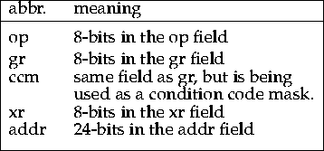
The instruction fields are referred in the meaning field by the following
symbols:

To make writing instructions easier and more clear the mnemonic form
| op gr,addr[xr] |
For the notes in general (unless specified some other way)
hexadecimal numbers are written with a prefix of `0x'.
Octal numbers are written with a prefix of `0',
and numbers just standing alone are usually decimal,
unless that makes no sense.
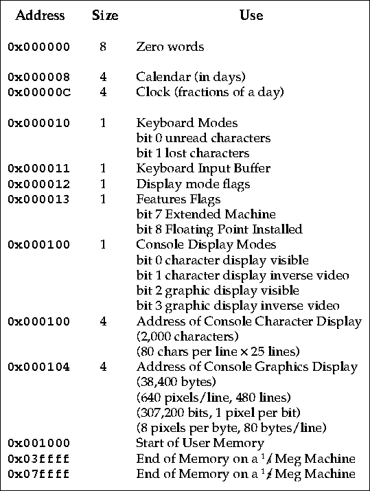
A small portion of memory is reserved for special use.
The first eight bytes of memory are always zero.
This is because commonly programmers make mistakes and accidentally
have their programs store, load, or execute the data at the
beginning of memory.
By defining these words to be zero with nothing depending
on the data, detection and correction of faulty programs is easier.
The memory contains a 32-bit clock word and a 32-bit date word. The calendar is a block of 4 bytes starting in location 8. The clock is in the folling memory word. The clock is automatically incremented every clock tick. The value in the clock word represents a count of time in 1/24,855.134ths of a second; so this counts to 231 in a single day.
The clock doesn't really tick that fast; the Hermes machine clock ticks 120 times per second, at each clock tick about 207 units are added to the clock. Some ticks add an additional unit or two to make up for lost fractional units that have accumulated to more than a clock unit. The clock is assumed to be synchronized to overflow, and reset to zero, at midnight GMT, the overflow is carried into the date register adding one to its value.
The calendar word is assumed to represent days since the midpoint of Julian Day 1 (midnight GMT). `Julian Days' is the name given to a calendar based on just counting days, it is commonly used by the astronomers to record significant dates. A recent reference point for Julian Days is Sun 13 Aug 1995 = JD2,449,943
The date and time can be reset by storing new values into the word
at location 8 or 12 (0x00000c) respectively.
Keyboard input is done a single character at a time.
If the bit 0x000010/0 is 1 then there is a new ASCII code
from the keyboard in byte 0x000011.
After a load which accesses the bit at 0x000011,
the bit at 0x000010/0 is reset to zero.
If a character arrives from the keyboard and the bit at 0x000010/0 is 1
then the program has failed to get the current character,
the bit at 0x000010/1 is set to 1 indicating a lost character.
The new character replaces the unaccessed one in the byte at 0x000011.
The bit at 0x000100/0 controls if the console character buffer
is displayed on the CRT device.
CRT character output is done by a program storing
ASCII characters in the proper part of console character display buffer.
They will become visible as soon as they are stored, or when the bit at
0x000100/0 is set to 1.
The CRT has white characters on a black background.
White and Black are inverted if the bit at 0x000100/1 is 1.
Byte 0x000100/2 controls if the console graphics buffer is displayed on the CRT device. Graphics character output is done by a program storing bits into the proper part of console graphics display buffer. They will become visible as soon as they are stored, or when byte 0x000100/2 is set to 1.
In the graphics buffer a one bit represents a white point and a zero bit is represens a black point. These are inverted if byte 0x000100/3 is 1. Bits stored sequentially in the buffer correspond to successive bits in a line in the display.
The console graphics buffer is about 20 times bigger than the console
character display buffer.

| Reserved Memory Locations |